|
|
Serial Modbus According to Chad |
|
Modbus is an industrial protocol to allow computer software to communicate with a PLC. This summary covers Modbus RTU and does not cover Modbus ASCII or Modbus TCP/IP but the basis is the same for all. Modbus uses a Master and Slave architecture. The Master device can query the Slave devices but not the reverse. Typically Modbus communication is Serial over a RS232 wiring scheme. |
||
Modbus Frame or Transmission |
||
Master Modbus Query : |
||
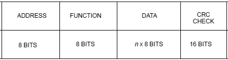
The Modbus RTU transmission frame consists of the slave address, modbus function code, data and a 16 bit CRC checksum in hexadecimal. |
||
 |
||
Address: |
||
Each slave must have a unique address between 1 and 247. |
||
Function: |
||
There are many functions available in Modbus and which functions are available are hardware dependant. Common functions are: 01 - Read Coil Status (Output) 03 - Read Holding Registers 05 - Force Single Coil 06 - Preset Single Register |
||
Data: |
||
A PLC has many functional sections such as IO, memory bits and memory words. Modbus has specific codes concerning these locations but the PLC Modbus communication hardware usually handles this transparently for you. The data portion of the query frame is just additional information (parameters) required for the function code if needed. |
||
CRC Check: |
||
This is just a CRC16 checksum or error check calculated from the Modbus frame and append onto the end of the frame before transmission. The slave device will double check the checksum against the frame. If it doesn't match an error response will be sent and the function rejected. |
||
Example Modbus Master Queries: |
||
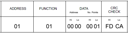
Function 01 - Read Coil Status: Data required for this function is:
|
||
Description: Read the status of output 1 on slave device 1. |
||
 |
||
Code Example: Data = Chr(1) + Chr(1) + Chr(0) + Chr(0) + Chr(0) + Chr(1) Data = Data + Chr(CRC_High) + Chr(CRC_Low) |
||
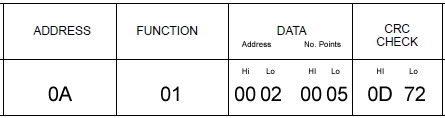
Description: Read the status of outputs 3 to 7 on slave device 10. |
||
 |
||
Code Example: Data = Chr(10) + Chr(1) + Chr(0) + Chr(2) + Chr(0) + Chr(5) Data = Data + Chr(CRC_High) + Chr(CRC_Low) |
||
Additional Information |
||
I will be adding more to this as time allows. Here is a link to one of the best technical documents I could find on this subject. |
||
The best way to contact Chad is by email at info@protechs-online.com. |
||