|
|
PLC Programming |
|
Biomass Gasifier |
||
 |
||
This was one of the most challenging PLC projects I have been involved in. I had to create a biomass gasification process that would burn different biomass cleanly and efficiently. Accomplishing this was a personal highlight for me. My PLC programming experience is ladder logic using contact language. |
||
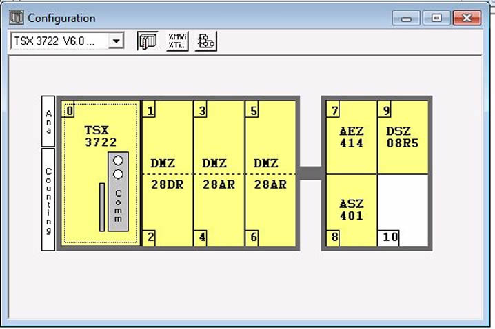
Modicon PLC TSX 3722 |
||
TSX 3722 Features:
|
 |
|
PL7 4.5 Graphcet Example |
||
PL7 Graphcet has three sections that are scanned in the order below.
After the three Graphcet sections are scanned then the rest of regular sections are scanned. The "Sr" folder is where subroutine logic is stored to be called by your ladder logic in other sections. |
PL7 Application Browser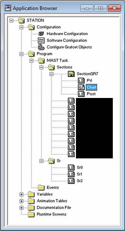 |
|
The Prl section is typically used to gather IO states for use subsequent sections. These always true ladders cause subroutines SR0, SR1 and SR2 to be scanned. |
PL7 Graphcet Prl Section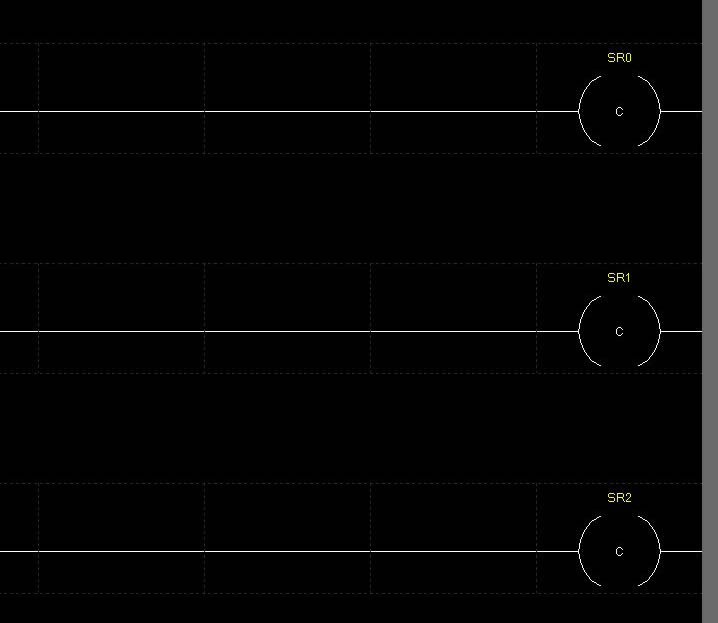 |
|
This is the first two rungs of subroutine SR0.
|
PL7 Subroutine Example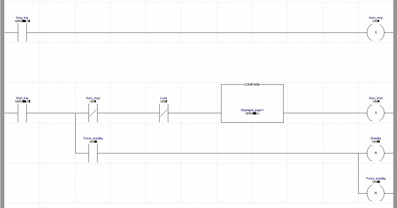 |
|
A Graphcet chart is more than a visual representation of an automated process it also control the process flow of the automation application. PL7 Graphcet Chart Components:
|
PL7 Graphcet Chart Section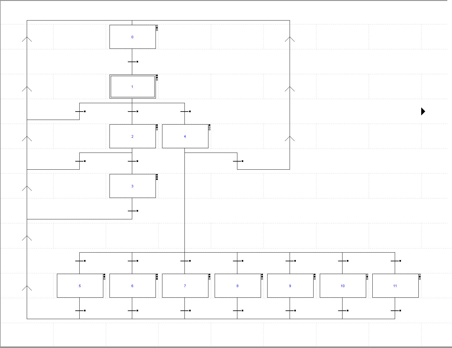 |
|
A PL7 Graphcet step has three parts.
|
PL7 Graphcet Step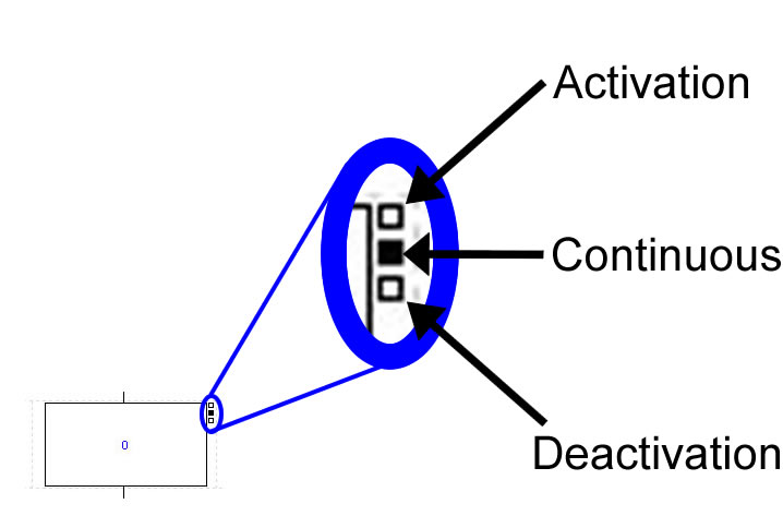 |
|
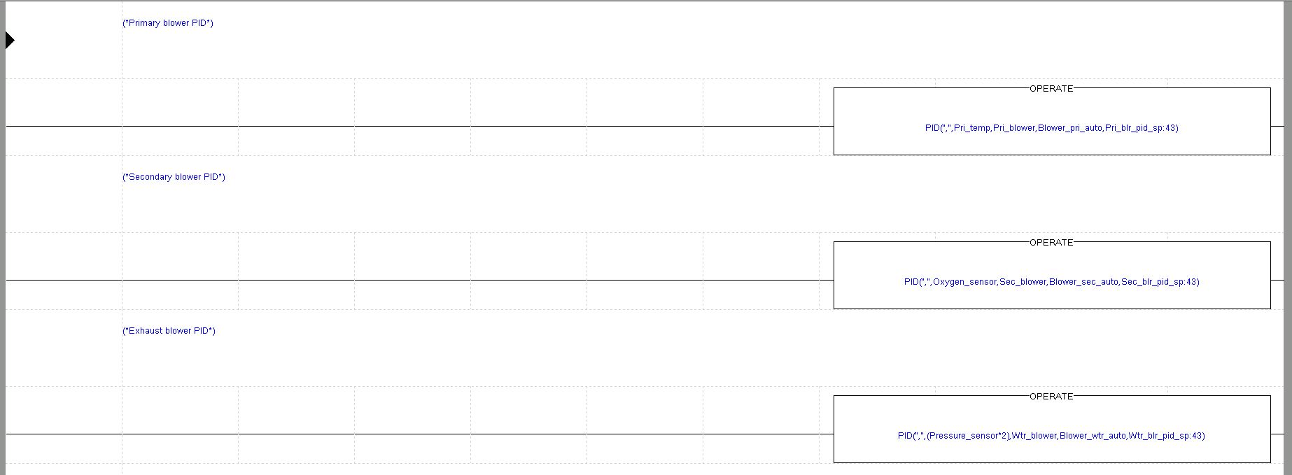
PL7 PID Example
|
||
The best way to contact Chad is by email at info@protechs-online.com. |
||